


RACE against the machine, I mean Arduino!
One of the controllers on my daughter's slot car set broke. So instead of fixing it, we thought it would be cool to replace it with an Arduino, and race against the machine!
On face value, this seemed like an easy thing to tackle, but after getting all the electrics and wiring done, the hard part was the timing of the actual car.
The track that we are using is a cheap set picked up at one of our local stores about a year back. We had it for a few weeks, when one of the controllers, the little thumb press multi-resistor thingies broke. The wires fell apart inside of it, and I'm pretty sure this will happen the other one too.
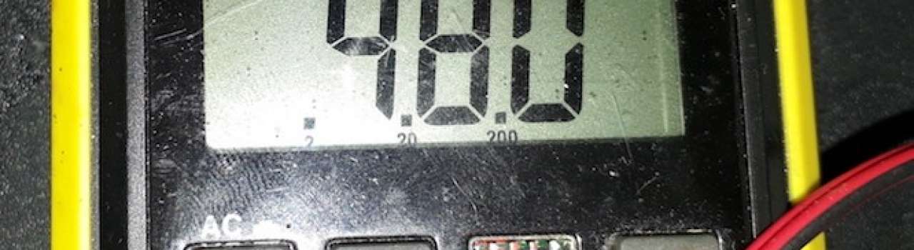
The first thing I did was replace the battery pack with an old 10V transformer; I've got a bunch collected over the years. This worked well and gave the cars more speed. Evidence of this was the distance they flew through the air on the first try.
The second thing we tried, was to replace the broken controller with a 10k potentiometer. This was a failure, one of those; I smell smoke, I need to order new parts, failures. So there was only one thing to try, grab a DC motor controller and control the car's speed, this worked great.
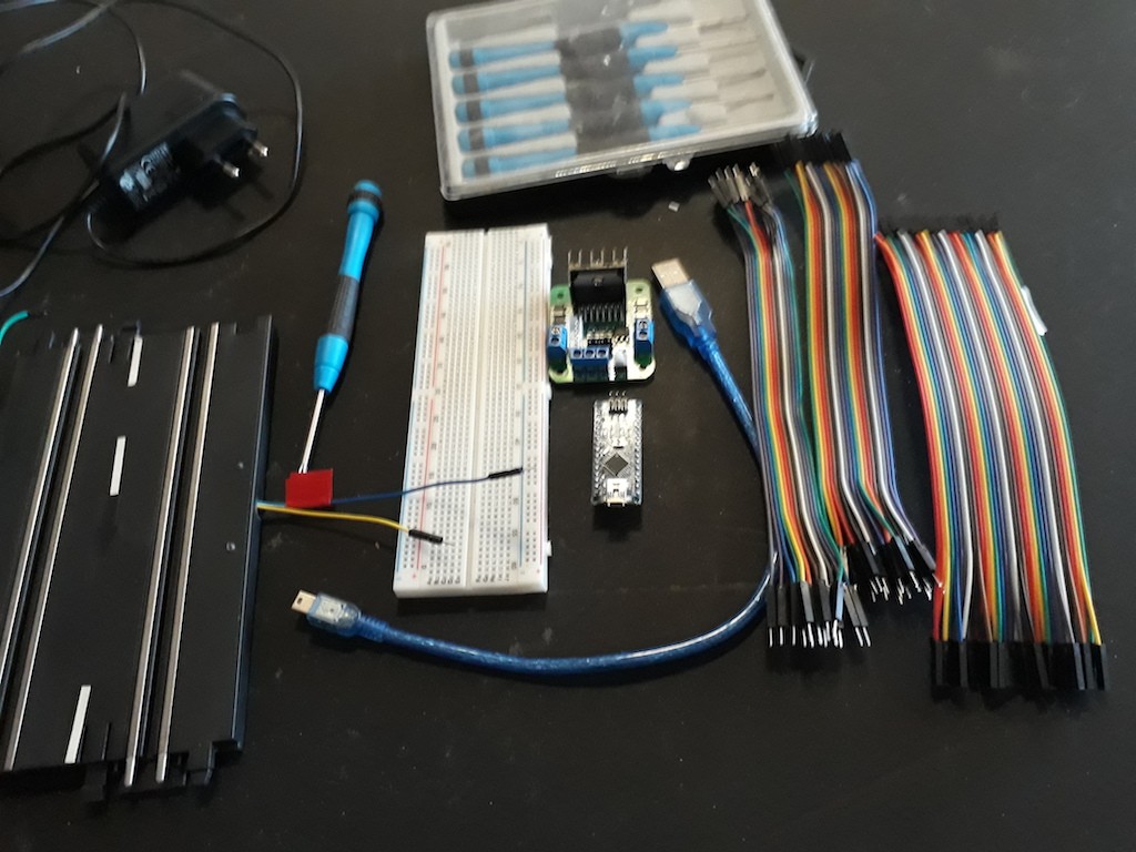
Here are the parts that you need.
- Slot car set. Yip, your Arduino controlled slot car project will need this!
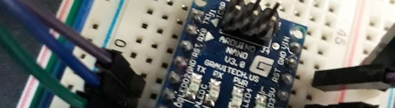
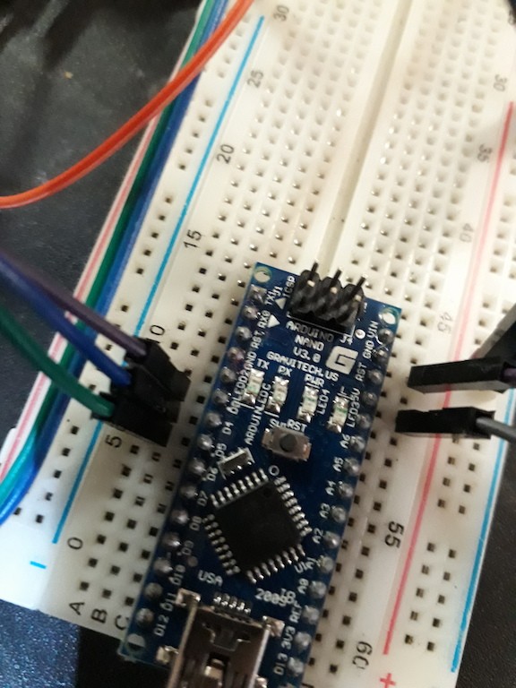
- An Arduino. I used a Nano, but any one will work.
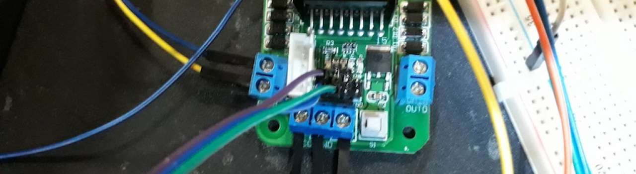
- A DC motor controller that can take +10V.
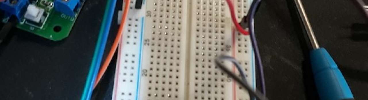
- Breadboard.
- Jumpers.
- Small screwdrivers.
- Solder and Soldering Iron.
- Wire cutters.
- Voltmeter (Optional).
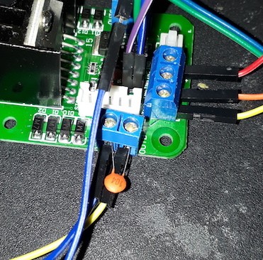
- 1 x 10⁴p Capacitor to smooth out the PWM (Optional)
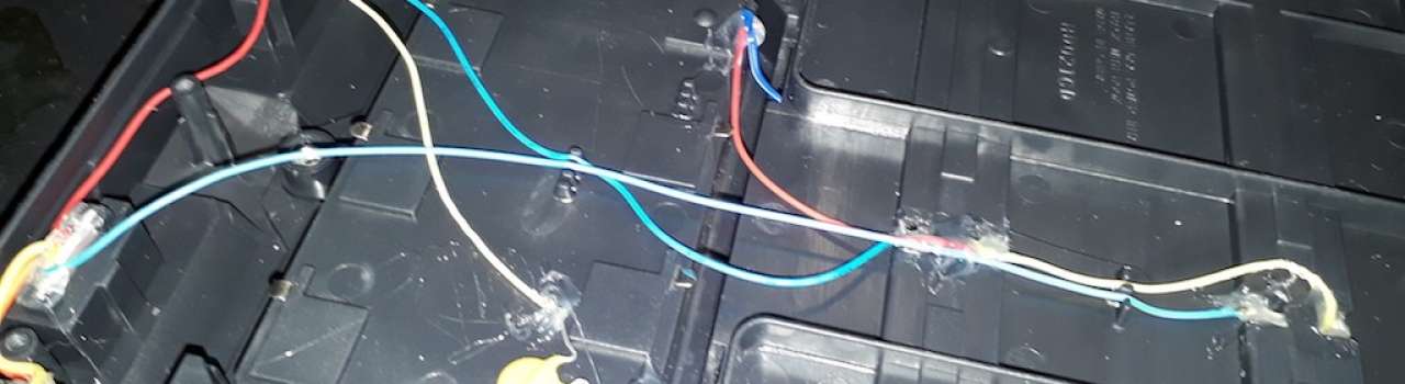
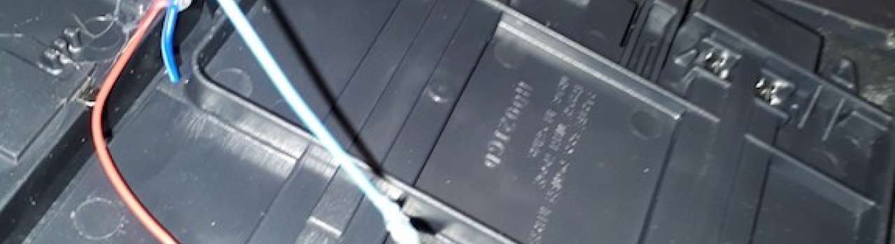
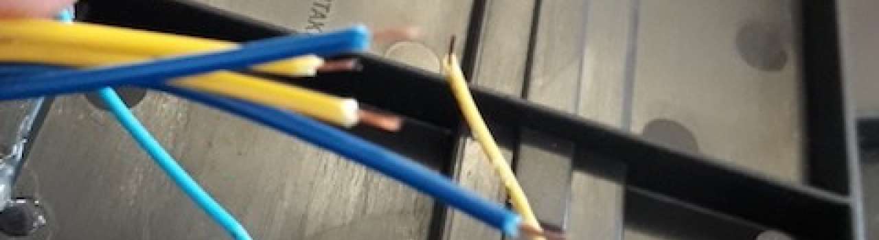
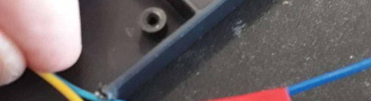
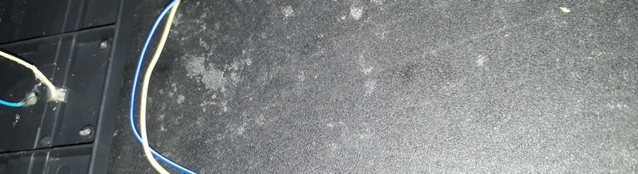
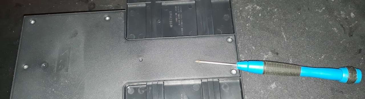
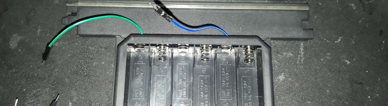
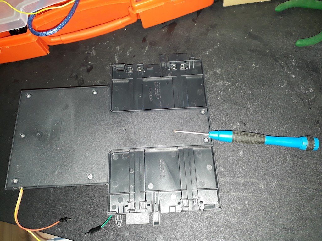
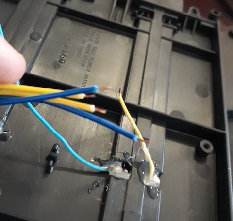
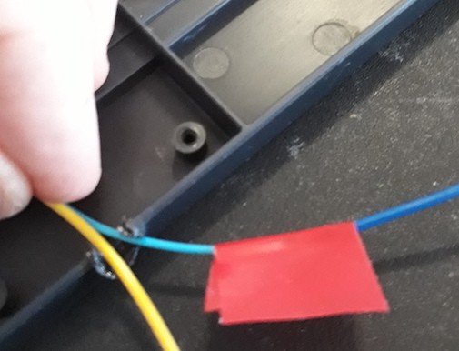
To start, remove the Battery Pack and the piece of track that connects to the power supply and controllers. Flip it over and remove any screws hiding the electronics. You will see on these images the wires that I added to use a 10V power pack and the potentiometer mentioned earlier.
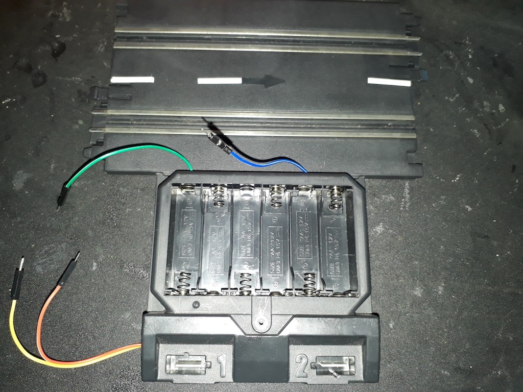
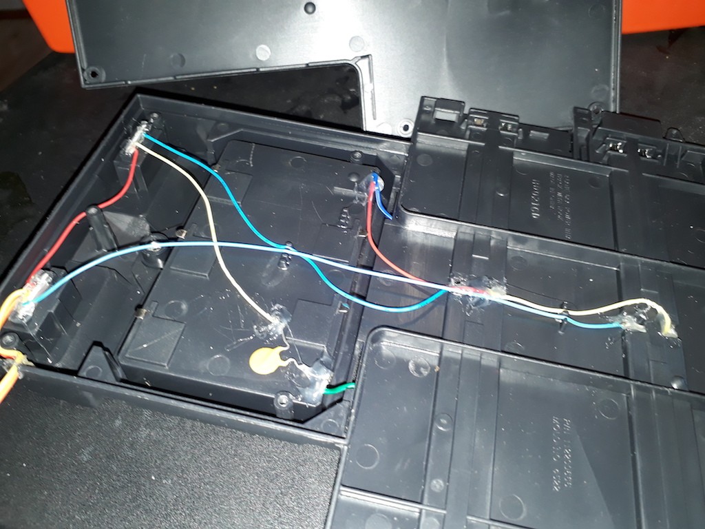
This slot car track has two slots. You will notice one of these slots is used as common ground. Focus on the other slot, it only has two wires.
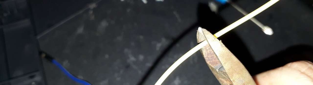
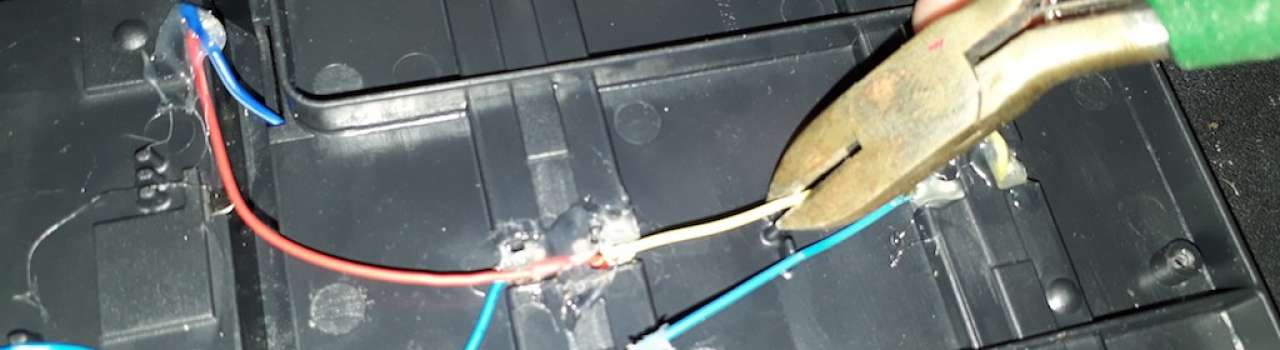
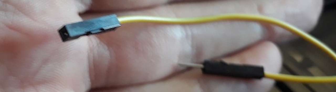
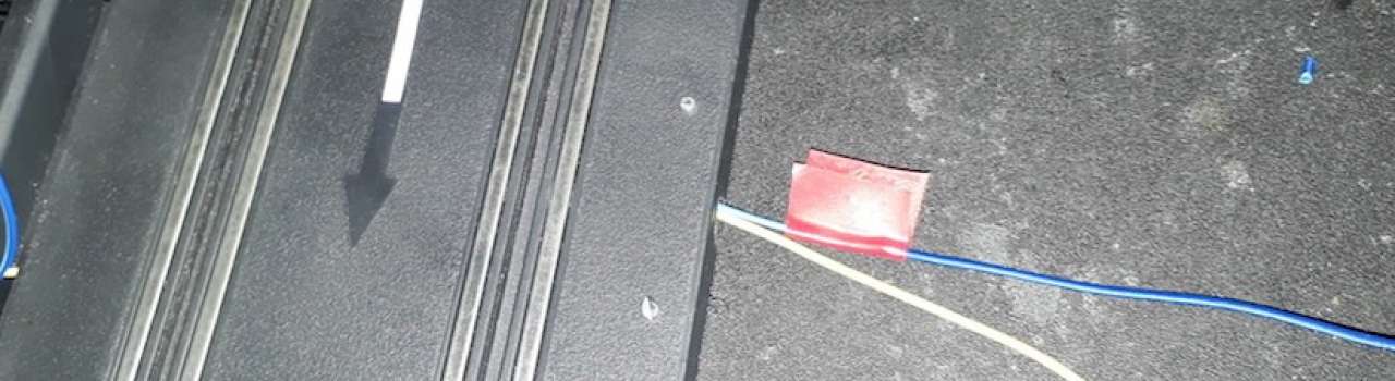
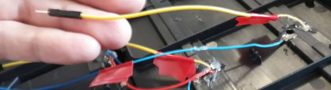
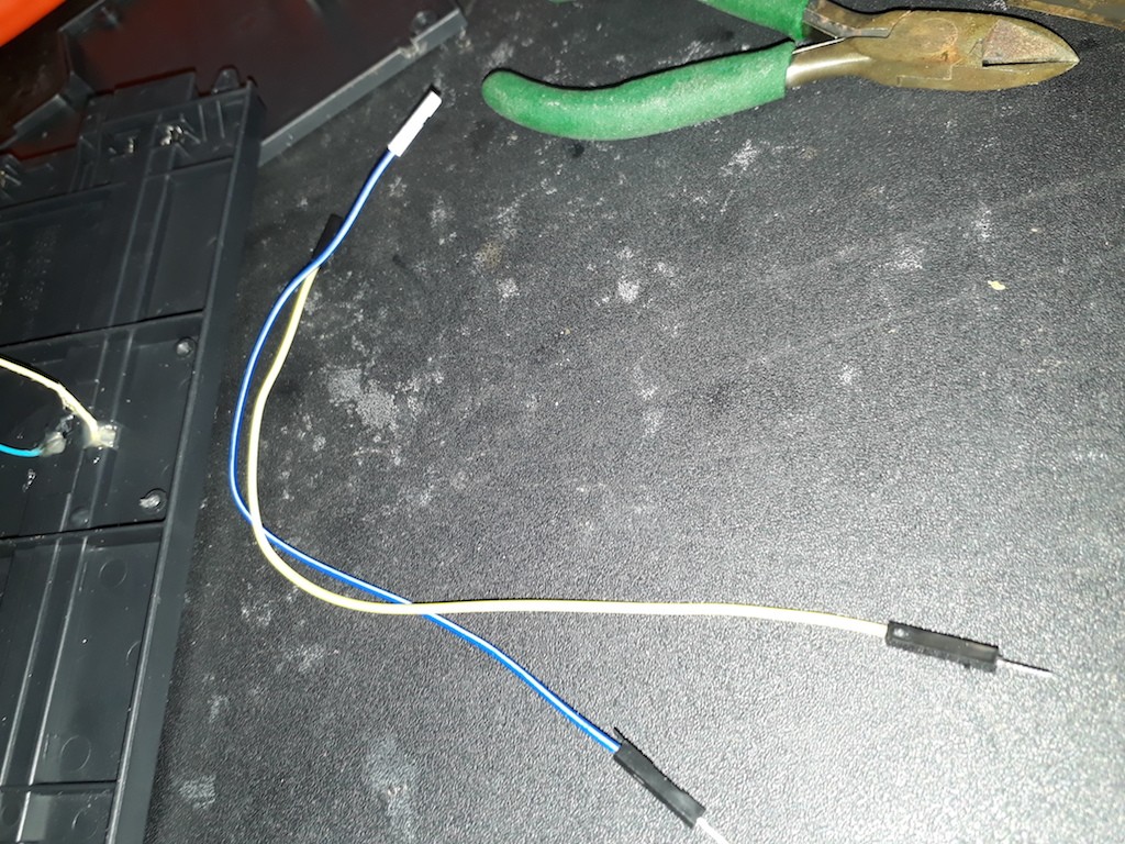
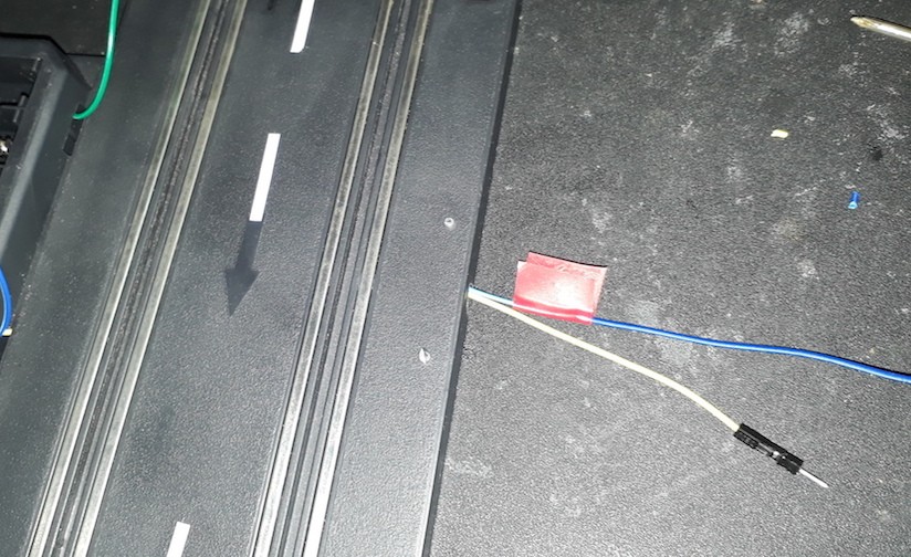
We might want to undo this conversion, so I took two male-female breadboard jumpers and cut them in half. These are then soldered so that a controller can be used later by reconnecting the jumpers.
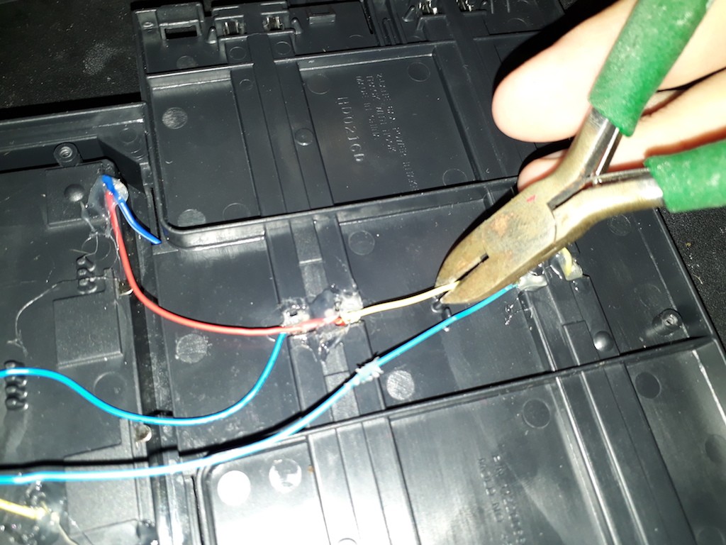
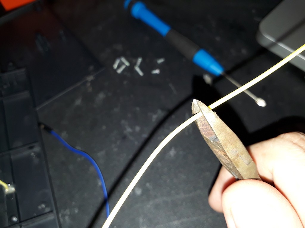
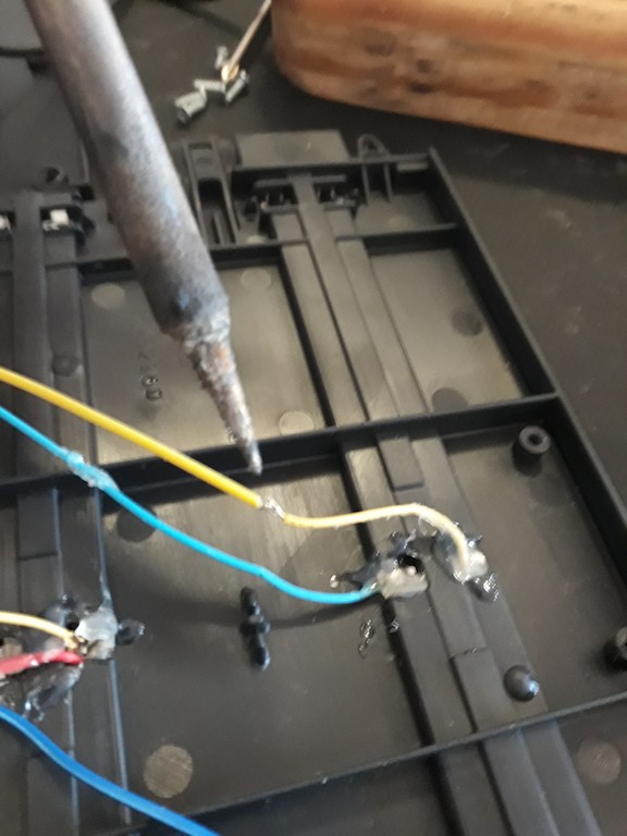
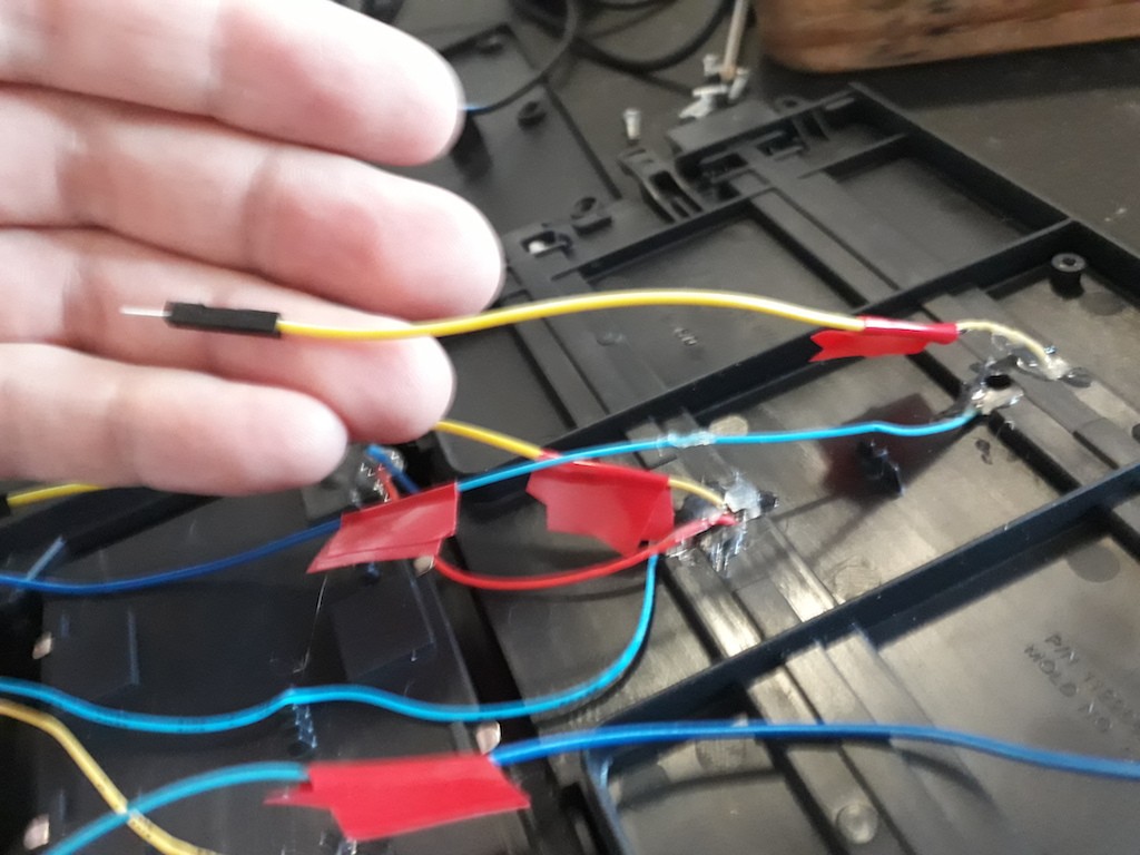
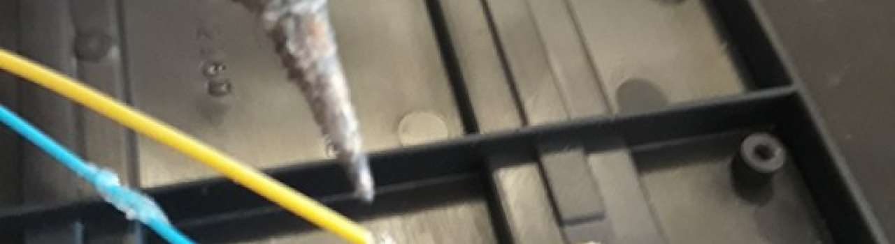
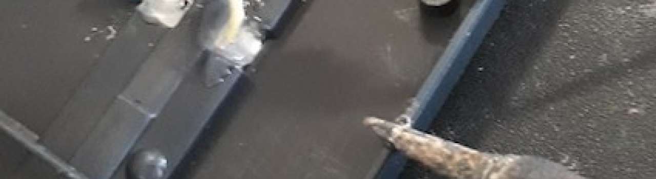
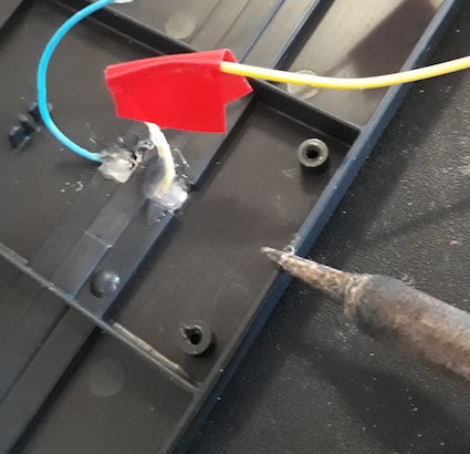
After this, using my old soldering iron, I melted a groove into the track to fit the new wires. Added a bit of insulation tape, then screw the cover back on.
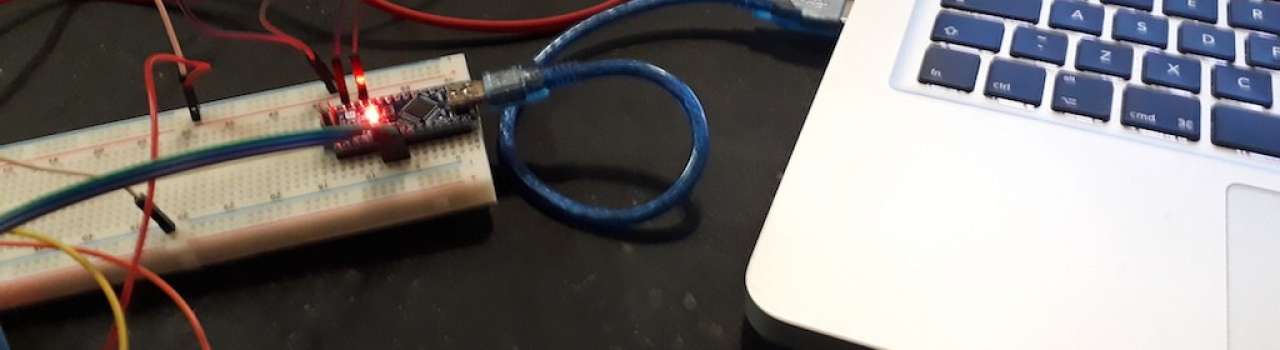
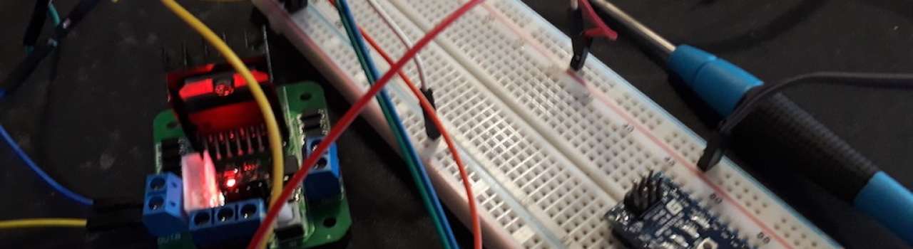
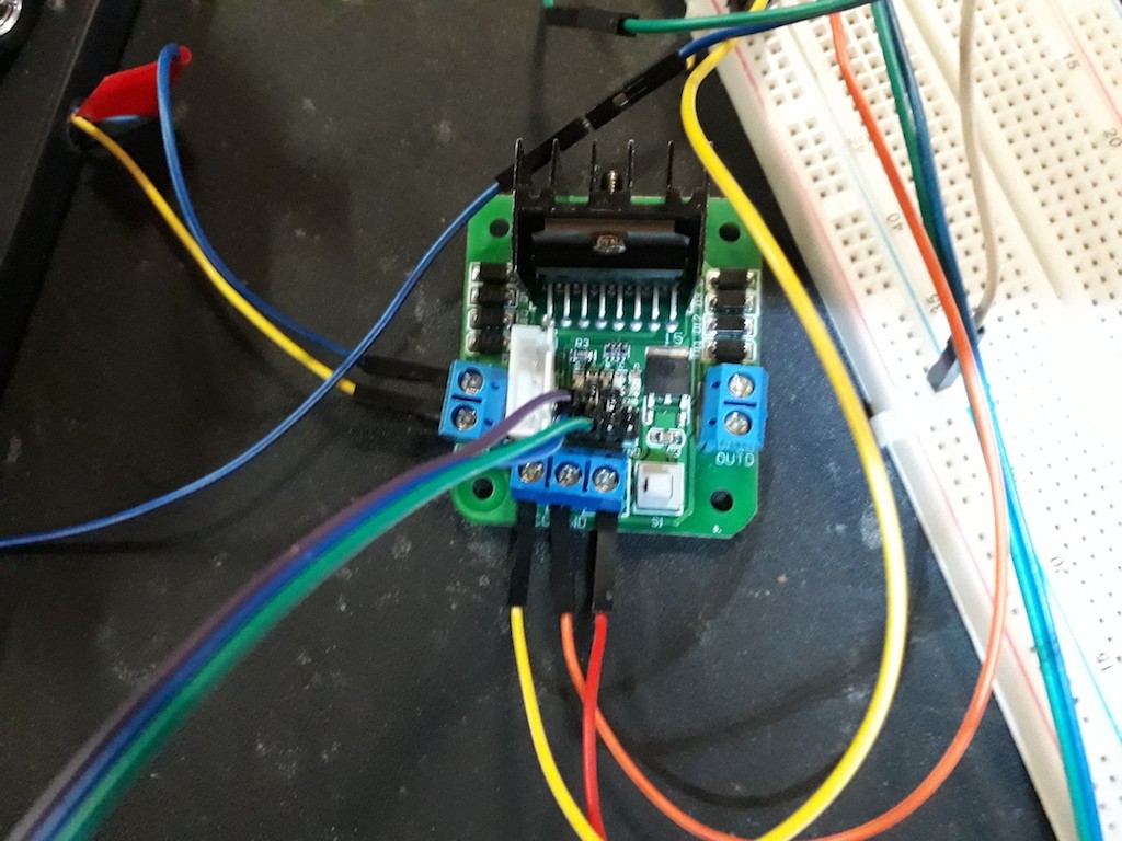
Now we are ready to plug in the Adriano board and Driver board. Here's what we need.
I connected it up, so that the 10V power supply powers the driver board, then from the driver board, you power the Adriano Nano.
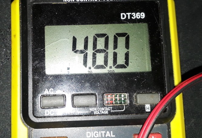
All components have a common ground, but make sure not to plug the 10V directly into the Arduino 5V, or you will get that,
Oh No, I need to order more parts smoke.
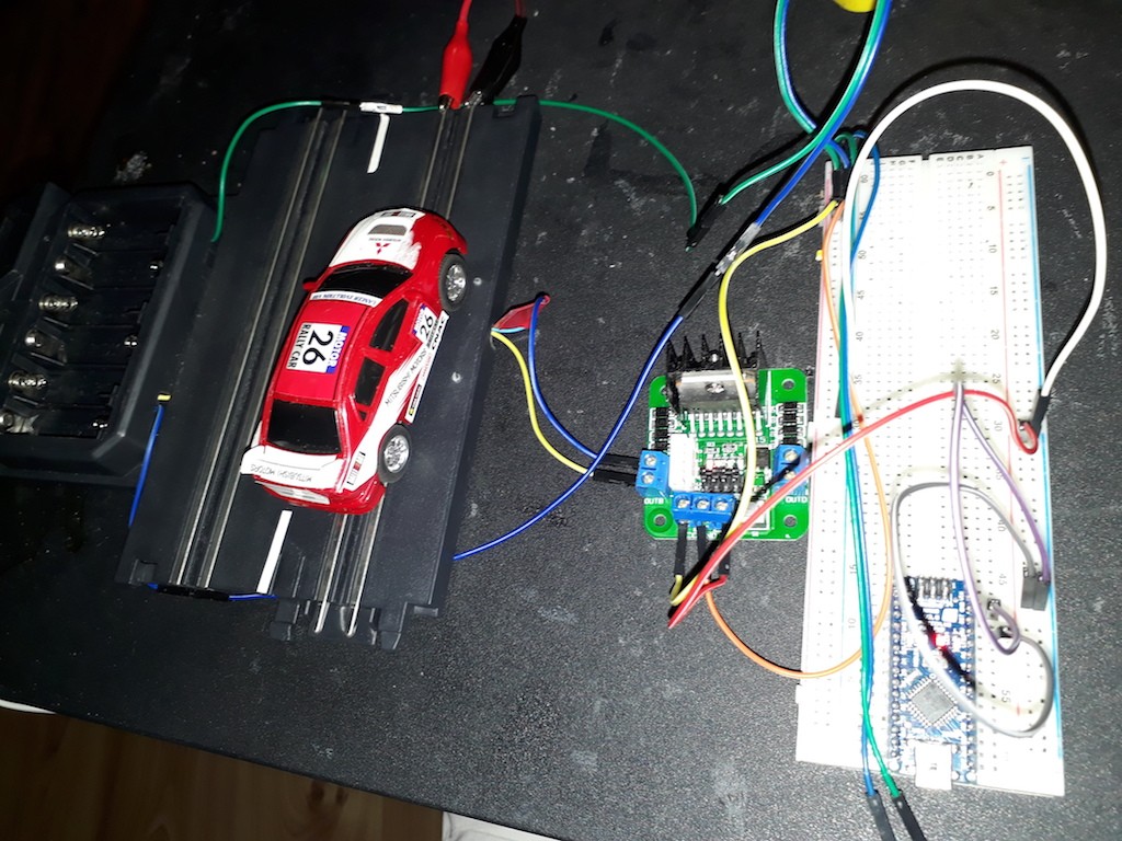
I used the driver board's 5V out and plugged it into the Arduino 5V pin because it's nicely regulated. You could plug the 10V directly into the Arduino Vin pin, but given that the slot track will have two cars running, one with the variable resistor, I wasn't sure how that would fluctuate the voltage.
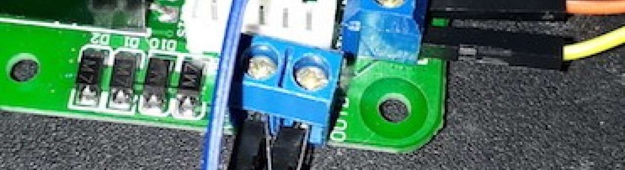
Now that all the power is connected, take three Male-Female jumpers and connect the Driver Board's Speed pin to a PWM pin on the Arduino, I used D3.
Then the forward and reverse pins on the driver board are connected to any other digital pins; I used D4 and D5.
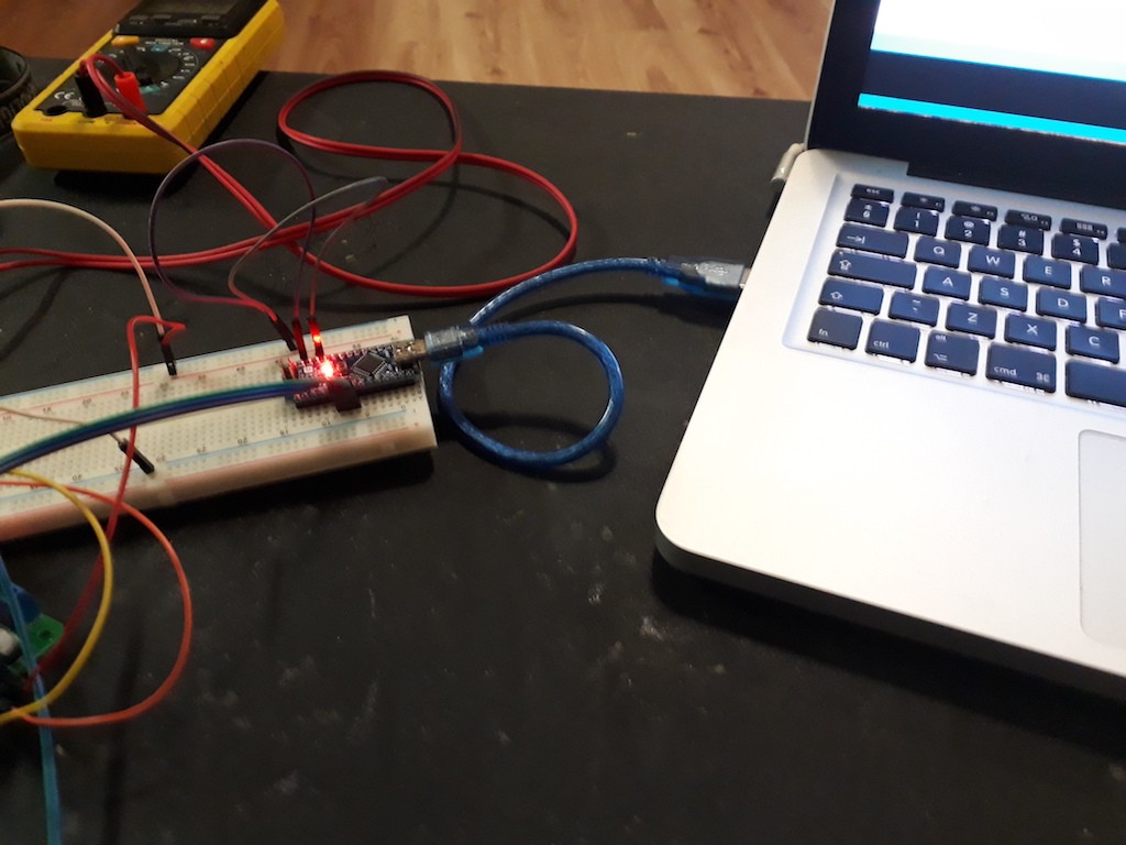
Now you are ready to tackle the software.
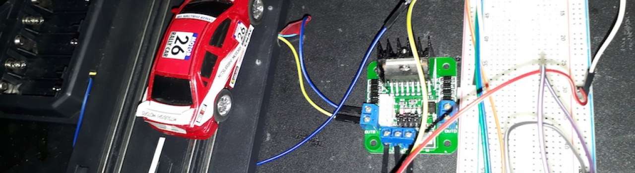
Connect your piece of track back to the main track, and position everything so you can make changes to the Arduino Code and run tests on the track as you go.
The basic logic is, set all three used pins to output, then set the direction once in the setup, unless you want to jam the cars into reverse just for fun.
That would be cool to try! To set direction, set one of the direction pins to HIGH then the other to LOW.
Now start slow! I ended up with a slot car almost cracking a window on the first go. You will notice that if you set the speed too low, the car will make a noise but not move.
This is because of the PWM. To help this connect a capacitor across the power out terminals on the driver board. This will allow your car to crawl a bit better.
Now it's up to you. You add speed settings and delays in your loop according to your track. It's trial and error. You could add a hall sensors under the track to pick up the slot car magnet and trigger speed settings, but it's not needed once you've got the times and speeds dialled in. Something that helped, was to turn the LED on and off at important parts of the code. You can then visually see the timing as the car does laps.
Until the next time, have fun.
The code I used on my track.
int SpeedPIN = 3;
int DirectionPIN1 = 4;
int DirectionPIN2 = 5;

void setup() {
 pinMode(SpeedPIN, OUTPUT);
 pinMode(DirectionPIN1, OUTPUT);
 pinMode(DirectionPIN2, OUTPUT);

 digitalWrite(DirectionPIN1, HIGH); //Set default direction
 digitalWrite(DirectionPIN2, LOW);
}

void loop() {
 analogWrite(SpeedPIN, 80); //first bend start
 delay(1000); //first bend stop
 digitalWrite(13, HIGH); //LED to show start of acceleration
 analogWrite(SpeedPIN, 250); //Go FAST start loop
 delay(335); //Go FAST end loop
 digitalWrite(13, LOW); //LED off to show finished accelation
 analogWrite(SpeedPIN, 50); //SLOW for Second bend
 delay(1100); //SLOW for Second bend
 analogWrite(SpeedPIN, 60); // Speed up slightly
 delay(1400); //Start again
}

Leave a comment